
HTE.PS series transmitters are designed to measure relative humidity and temperature of compressed air under pressure up to 16 bar. For process connection, the transmitter is equipped with a G1/2″ thread.
HTE.PS transmitters with RS-485 interface can calculate dew point temperature both under normal atmospheric pressure DP (Dew Point) and under overpressure PDP (Pressure Dew Point).
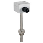
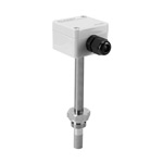
Capabilities of transmitters with RS-485 interface (Modbus RTU protocol):
| Modification | HTE.PS | |
|---|---|---|
| Relative humidity | ||
| Relative humidity readings (measurements) range | 0 to 100% (5 to 95%) | |
| Absolute error limit (at ambient temperature +25 °C and 1 m/s airflow velocity) | ±3% | |
| Response time (63% with standard protective cap HTE Cap.02, 1 m/s airflow) | 9 s | |
| Response time (95% with standard protective cap HTE Cap.02, 1 m/s airflow) | 30 s | |
| Temperature | ||
| Temperature measurement range depending on design | -40…+80 °C (for transmitters with digital output) * | |
| LimitsAbsolute error limit | ±0.8 °С | |
| Electrical characteristics | ||
| Output analog signal range * | 4…20 mA (0…20 mA) (direct current) 0…10 V (0…1, 0…3, 0…5 V) (voltage) |
|
| DC supply voltage depending on the output signal type |
24 VDC ±5% (nominal value for all modifications) 10…30 VDC (4÷20 mA) 5…30 VDC (0÷1 V, 0÷3 V or a digital output) 7…30 VDC (0÷5 V) 13…30 VDC (0÷10 mA) |
|
| Power consumption ** |
4.3 mA (for transmitters with current output) 4.7 mA (for transmitters with voltage output) 6.2 mA (for transmitters with RS-485) 6.4 mA (for transmitters with RS-485 and voltage output) |
|
| Allowable load resistance for current output | see Allowable load resistance of current output | |
| Minimum load for voltage output |
1 kΩ (0…1 V) 3 kΩ (0…3 V) 5 kΩ (0…5 V) 10 kΩ (0…10 V) |
|
| Digital output interface | RS-485 (Modbus RTU) | |
| Maximum allowable cable length | 1000 m | |
| Other characteristics | ||
| Connection thread | G1/2″ | |
| Weight | 200 g | |
| Ingress Protection | IP40: housing IP20: sensor |
|
| Transmitter material | ||
| Protective cap | stainless steel AISI 304 | |
| Housing | ABS plastic (grey) | |
| Measuring probe | AISI 304 stainless steel | |
| Operating conditions | ||
| Minimum air flow rate | 1 m/s | |
| Ambient temperature | -40…+80 °C | |
| Operating pressure | 0 to 16 bar | |
| Relative air humidity | max 100% | |
| Polling period (for transmitters with digital signal) | ≥ 1 s | |
* - User configuration is available for transmitters with RS-485 interface.
** - At 24 VDC supply voltage without analog and digital output signals connected. RS-485 load is 120 Ω.
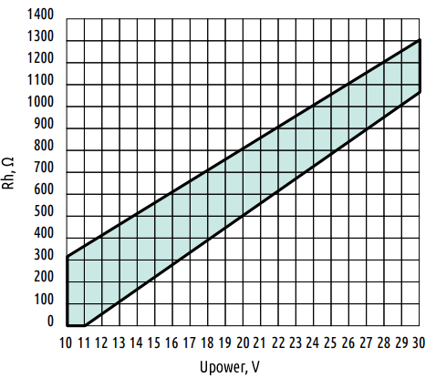
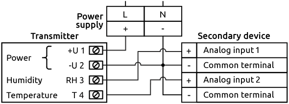
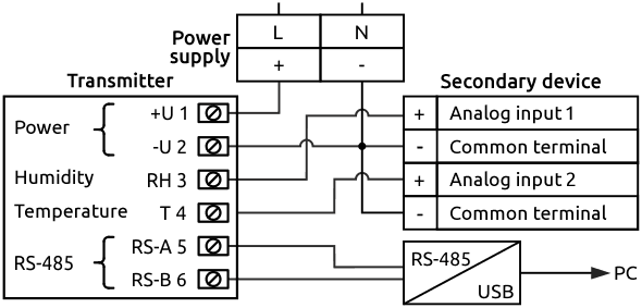
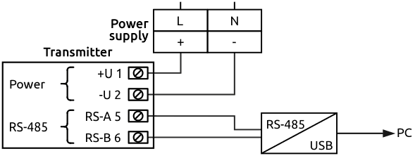
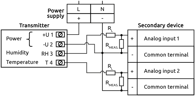
Attention! When connecting the device current outputs, add an external load resistor (RL) in series with the instrument’s measuring input resistor (RMEAS.). Choose RL so that the sum RMEAS. + RL stays within the permissible load range at the given supply voltage (see the external wiring diagram for HTE.PF‑I…). This reduces the influence of self-heating. For example, for a 24 VDC supply voltage, the sum of the resistances RMEAS. and RL must be between 700 Ω and 1 kΩ.
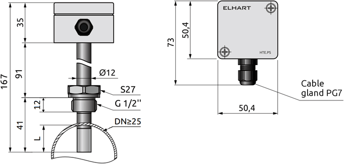
L — recommended minimum immersion depth of the sensor into the pipeline is 15 mm.


