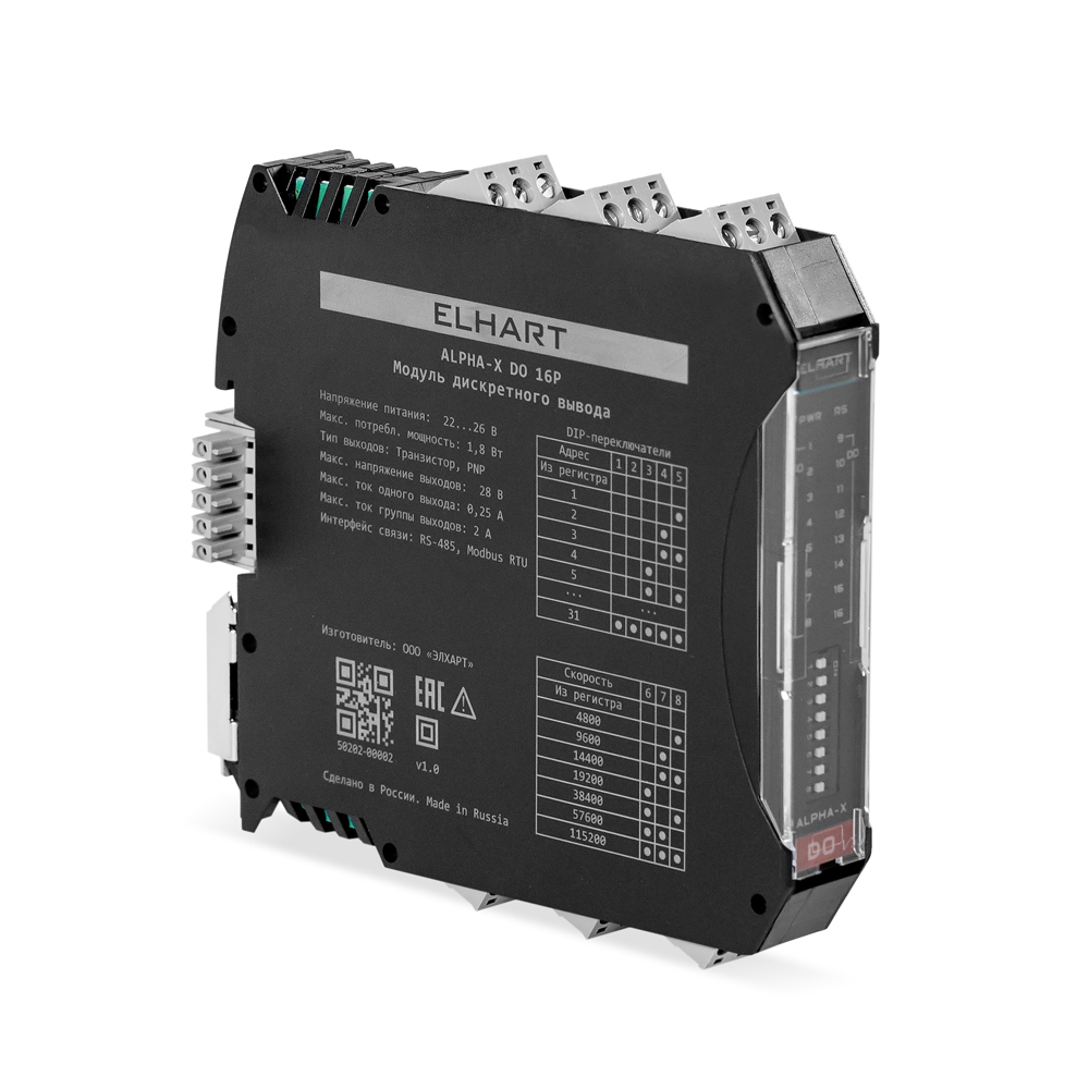
Alpha-X digital I/O modules are designed to read logical states from external sensors and devices (digital inputs), and to switch or control external equipment using physical contacts (digital outputs).
Ideal for PLC I/O expansion, these modules communicate via RS-485 using Modbus RTU. This ensures native compatibility with ELHART PLCs and any third-party, Modbus RTU-compliant controllers.
Easily configure your devices with the free ELHART Configurator software.
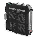
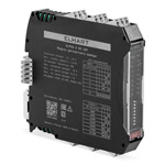
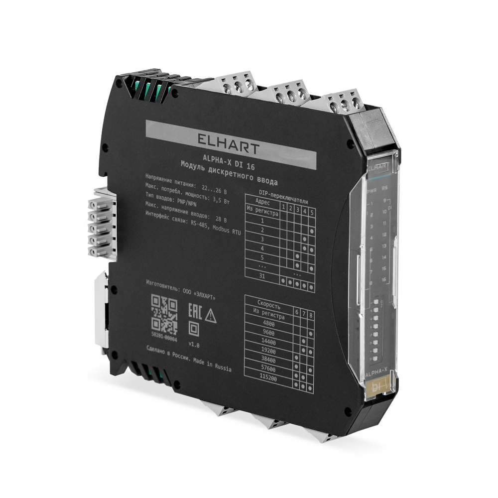
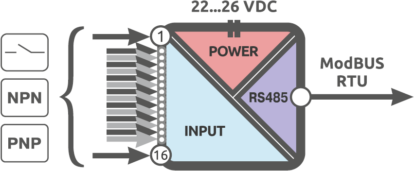
Alpha-X DI 16 features 16 digital inputs for devices with PNP, NPN and dry-contact output type. Connected devices require an external power supply. Each group of four inputs has a 32-bit counter. Incrementing and decrementing inputs can accept pulse signals up to 4 kHz. The module communicates with your controller via Modbus RTU — with three-way galvanic isolation and DIP switches for communication setup.
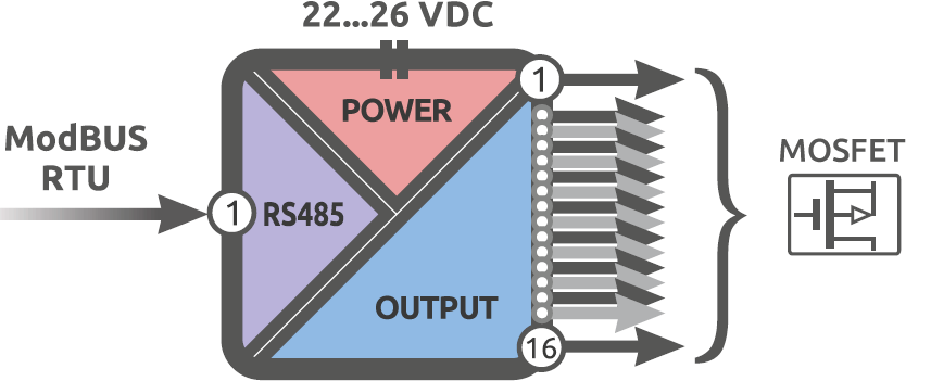
Alpha-X DO 16P features 16 digital outputs divided into two groups. MOSFETs are used as switching elements, with a common terminal within each group. Each output can generate a PWM signal with a minimum pulse width of 200 ms. Outputs are controlled via Modbus RTU. To protect connected devices, three-way galvanic isolation is provided (power / communication interface / digital outputs).
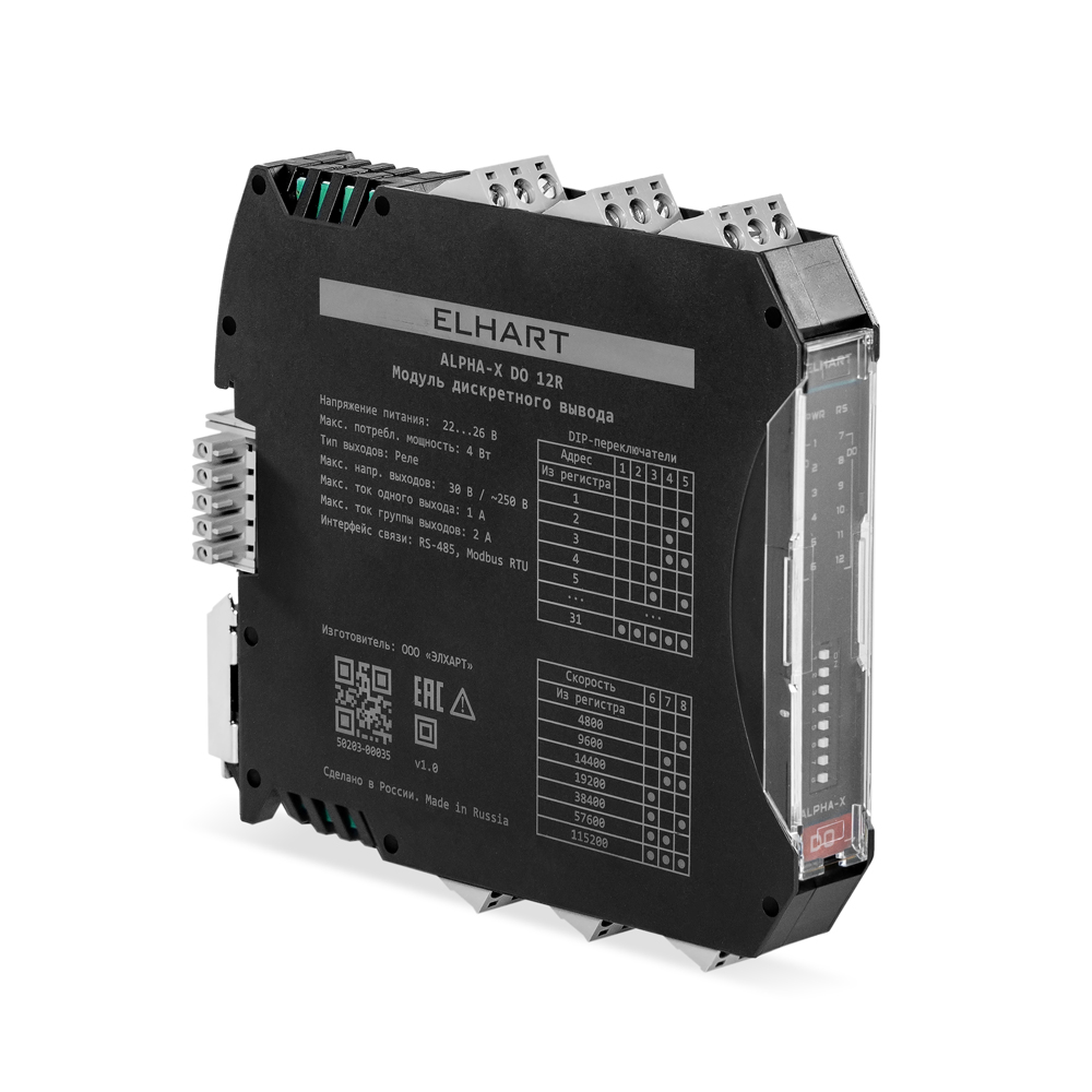
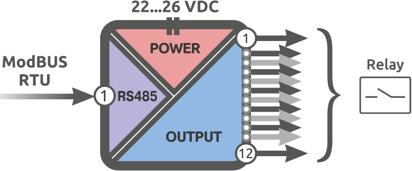
Alpha-X DO 12R features 12 relay outputs to control external devices depending on digital signals from SCADA systems or PLCs. Each relay output can switch AC voltage up to 250 V supplying a resistive load with current consumption up to 1 A. The module has three-way galvanic isolation and DIP switches for communication settings.
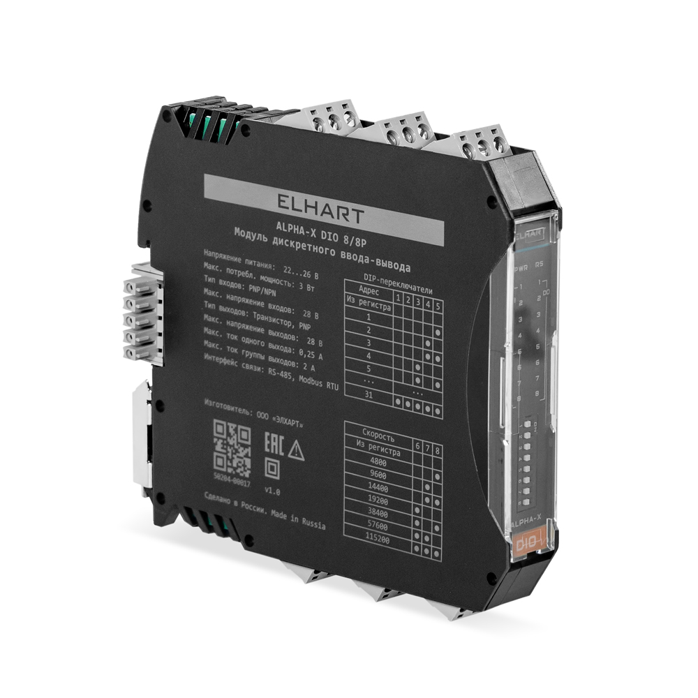
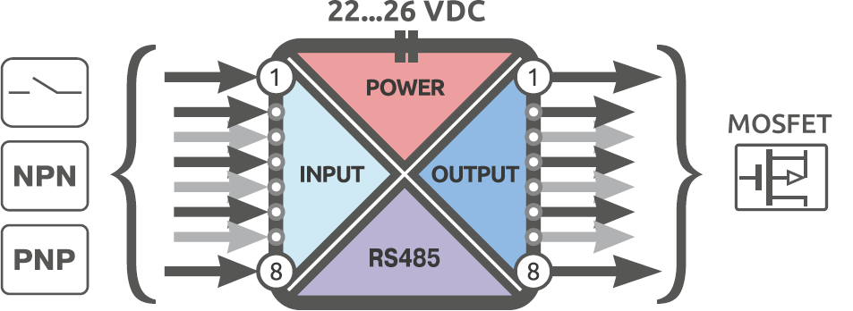
Alpha-X DIO 8/8P is a combined device. It has 8 digital inputs for PNP, NPN, or dry-contact sensors, and 8 transistor outputs. Output characteristics match Alpha-X DO 16P. Galvanic isolation is provided between the main module circuits (power / digital inputs / digital outputs / communication interface).
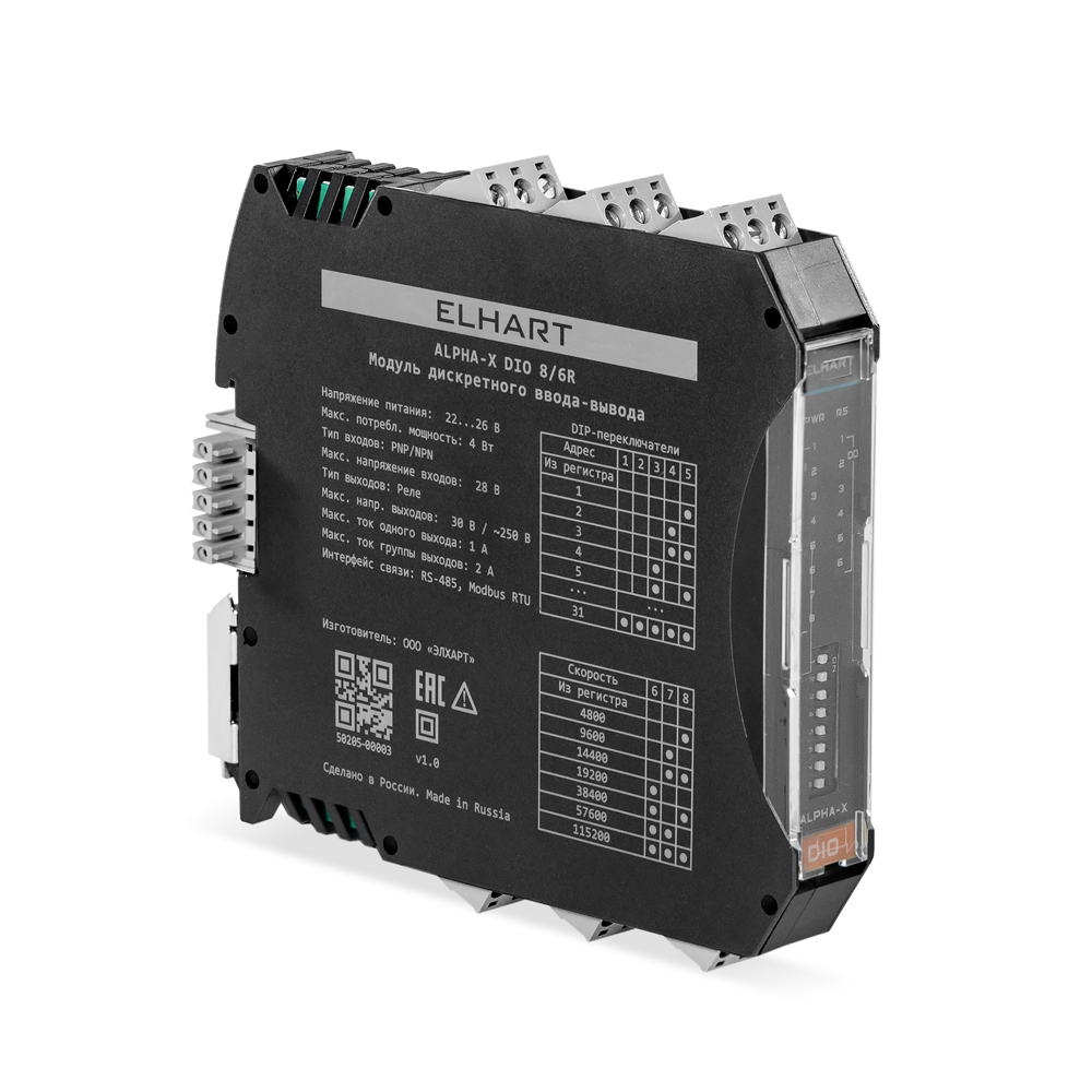
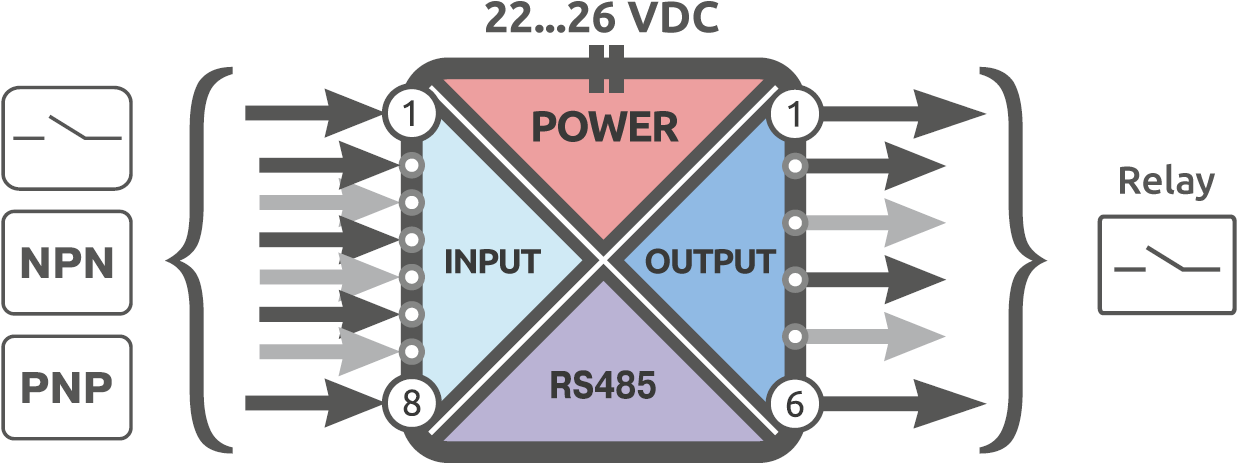
Alpha-X DIO 8/6R is the combined module with relay outputs. Relays can run in PWM mode as well — minimum period 1 s. Galvanic isolation is provided between the main module circuits (power / digital inputs / relay outputs / communication interface).
| Modifications | DI 16 | DO 16P | DIO 8/8P | DO 12R | DIO 8/6R |
|---|---|---|---|---|---|
| Maximum power consumption, W | 3.5 | 1.8 | 3 | 4 | 4 |
| Digital input parameters | |||||
| Types of connected sensors | PNP / NPN | ||||
| Maximum input switching frequency | 4 kHz | ||||
| Maximum current consumption of one input | 6.5 mA | ||||
| Logic 0 level (OFF) | 0...4 V | ||||
| Logic 1 level (ON) | 11...28 v | ||||
| Digital output parameters | |||||
| Output type | - | transistor, PNP | relay | ||
| Minimum pulse time | - | 200 µs | - | ||
| Voltage drop | - | 0.7 V | - | ||
| Maximum allowable voltage | - | 28 VDC | 250 VAC, 30 VDC | ||
| Maximum current of one output | - | 0.25 A (resistive load) | 1 A (resistive load) | ||
| Maximum current of output group | - | 2 A (resistive load) | 2 A (resistive load) | ||
| Parameter | Value |
|---|---|
| General | |
| Nominal supply voltage | 24 VDC (range 22…26 VDC) |
| Communication Interface | RS-485 |
| Supported protocols | Modbus RTU (Slave) |
| Interface baud rates | 2400, 4800, 9600, 14400, 19200, 28800, 38400, 57600, 76800, 115200, 128000, 256000 bit/s |
| Galvanic isolation of the interface | 1500 V |
| Ingress Protection | IP20 |
| Service life | 10 years |
| Operating conditions | |
| Operating temperature | -20…+50 °C |
| Relative humidity | 10...80% (without condensation) |

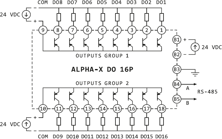
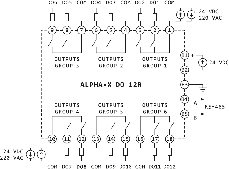
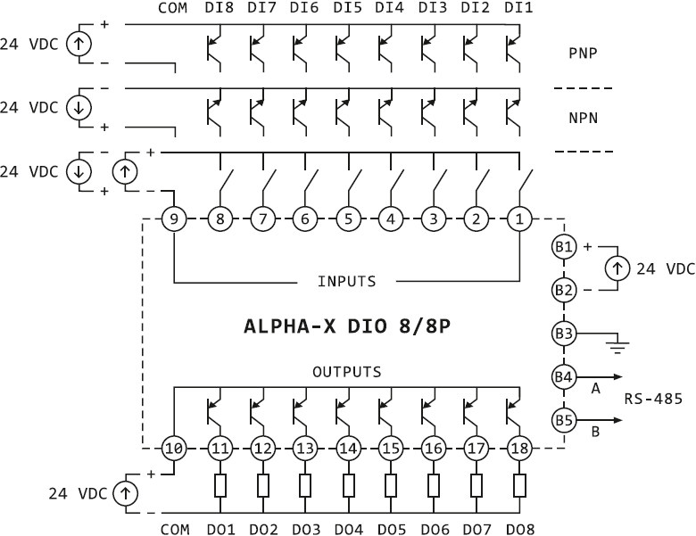
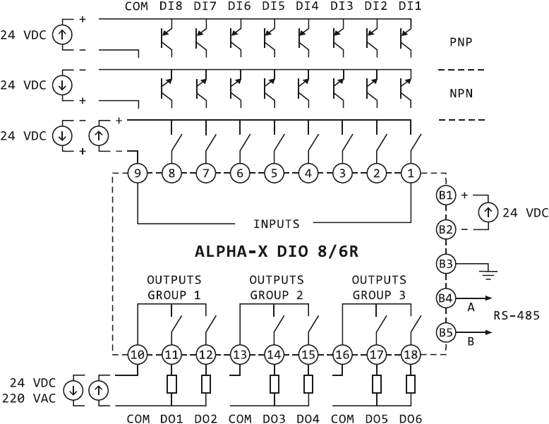
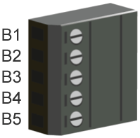
| Terminal | Description |
|---|---|
| B1 | Supply voltage, U (+) |
| B2 | Supply voltage, U (-) |
| B3 | Protective ground, GND |
| B4 | RS-485 interface, A (+) |
| B5 | RS-485 interface, B (-) |