EFS: flow switch

EFS: flow switch

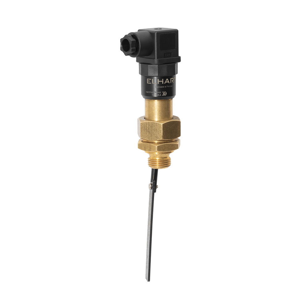
The EFS series flow switch is designed to monitor fluid movement in pipelines and protect equipment from dry running, overheating and emergency situations. It is used on pipelines ranging from DN20 to DN200 in systems with pressures up to 25 bar.

Features a magnetic actuation system, with no springs and mechanically wearing bellows.
Modifications Where to buy?

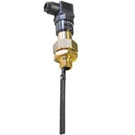
EFS-1-G12-D
EFS-1-G12-D
  • Design: brass, plastic, IP65
  • Process connection: G1/2′
  • Electrical connection: DIN 43650 connector
  • Features of the EFS flow switch
    • Universal installation: suitable for pipelines from DN20 to DN200.
    • Operating pressure: up to 25 bar.
    • Media temperature: -20 to +100 °C.
    • High ingress protection: IP65 (dust-tight and protected against water jets from all directions).
    • Reliability and durability: simple reed switch design with minimal mechanical wear parts ensures long service life.
    • High sensitivity: actuates even at low flow rates.
    • Minimal resistance: narrow paddle ensures minimal pressure drop and losses.
    • Complete kit: includes adapter nipple, paddle and mounting screw.
    • Simple electrical connection: via standard DIN 43650 connector.
  • Technical characteristics of the EFS flow switch
    Parameter Value
    Switching element type reed switch, NO contact
    Maximum switching voltage 48 VAC / 48 VDC
    Maximum switching current 1А
    Switching power max 10 Watts, VA
    Switching frequency max 100 Hz
    Contact resistance max 0.1 Ω
    Electrical connection DIN43650 connector with screw terminals up to 1.5 mm2
    Process connection G1/2″ male thread
    Operating pipeline diameters from 20 to 200 mm
    Replaceable paddle type PFS-P
    Media type liquid
    Media temperature range -20…+100 °C
    Media pressure max 25 bar
    Ambient temperature range (operation or storage) -20…+80 °C
    Relative humidity without condensation (operation or storage) max 95%
    Ingress protection IP65
    Total weight (with paddle and mounting screw) max 347 g
    Overall dimensions with paddle installed, LxWxH 226×57×36 mm
  • Connection diagrams for the EFS flow switch
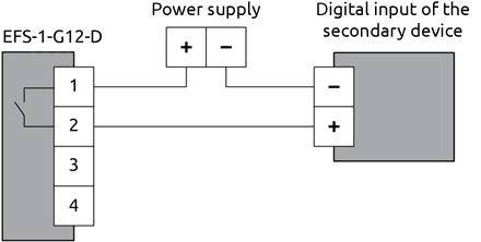
    Connection of electrical switch circuits - connection diagram
    EFS series switch connection diagram
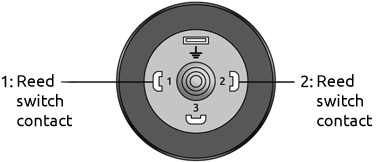
    Pin diagram
    Pin diagram
  • Overall dimensions of the EFS flow switch
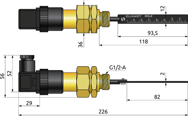
    Overall dimensions of the switch and the replaceable paddle, mm
    Overall dimensions of the switch and the replaceable paddle, mm