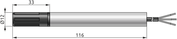
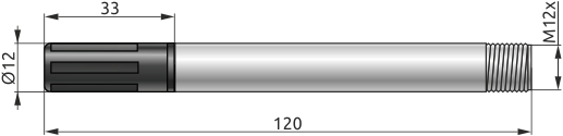
The HTE.PF-THI series transmitter is a digital temperature and relative humidity transmitter featuring automatic calculation of the Temperature Humidity Index (THI).
Modifications are available both with a 0...10 V analog output and an RS-485 digital interface (Modbus RTU protocol), and a modification with a 4...20 mA output. Readout of variables including temperature, humidity, THI, dew point temperature, and others is supported via RS-485.
Capabilities of HTE.PF transmitters with RS-485 interface (Modbus RTU protocol):
| Parameter | Value |
|---|---|
| THI | |
| THI to analog output conversion range * | 32.00…110.00 |
| Temperature | |
| Temperature measurement range * | -20…+80 °C |
| Absolute error limit | ±0.8 °С |
| Relative humidity | |
| Relative humidity measurement range | 0 to 100% (5 to 95%) |
| Absolute error limit (at ambient temperature +25 to +30 °C) | ±3% |
| Response time (63% with standard protective cap, 1 m/s airflow) | 8 s |
| Response time (95% with standard protective cap, 1 m/s airflow) | 30 s |
| Electrical characteristics | |
| Output analog signal range ** | 4…20 mA 0…10 V (0…1, 0…3, 0…5 V) |
| DC supply voltage depending on the output signal type | 12…30 VDC (for 4…20 mA output) 12…30 VDC (for 0…10 V output) |
| Digital output interface | RS-485 (Modbus RTU) |
| Maximum allowable length of RS-485 cable | 1000 m |
| Transmitter material | |
| Filter | ABS (black) |
| Housing | stainless steel AISI 304 |
| Filling compound | silicone |
| Other characteristics | |
| Transmitter length (depending on modification) | 116 mm: with cable 120 mm: with connector |
| Cable length *** | 1.5 m |
| Weight (depending on modification) | 78 g: with cable 34 g: with connector |
| Ingress Protection | IP67: housing IP20: sensor |
| Operating conditions | |
| Minimum air flow rate | 1 m/s |
| Ambient temperature | -40…+80 °C |
| Allowable atmospheric pressure | 86…106 kPa |
| Relative air humidity | max 100% |
| Polling period (for transmitters with digital signal) | ≥ 1 s |
(*) - The upper and lower limits of the output analog signals correspond to the display ranges for the THI and temperature channels (at factory settings).
(**) - Additional output signal ranges, which can be selected via the RS-485 interface.
(***) - For HTE.PF modification with cable.
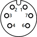
| Pin No. | Description |
|---|---|
| 1 | THI |
| 2 | Power supply: minus (-) |
| 3 | Power supply: plus (+) |
| 4 | Temperature |
| 6 | RS-485 B |
| 7 | RS-485 A |
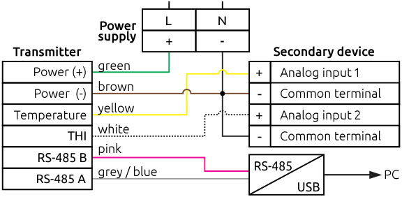
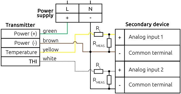
Attention! When connecting the device current outputs, add an external load resistor (RL) in series with the instrument’s measuring input resistor (RMEAS.). Choose RL so that the sum RMEAS. + RL stays within the permissible load range at the given supply voltage (see the external wiring diagram for HTE.PF‑I…). This reduces the influence of self-heating. For example, for a 24 VDC supply voltage, the sum of the resistances RMEAS. and RL must be between 700 Ω and 1 kΩ.