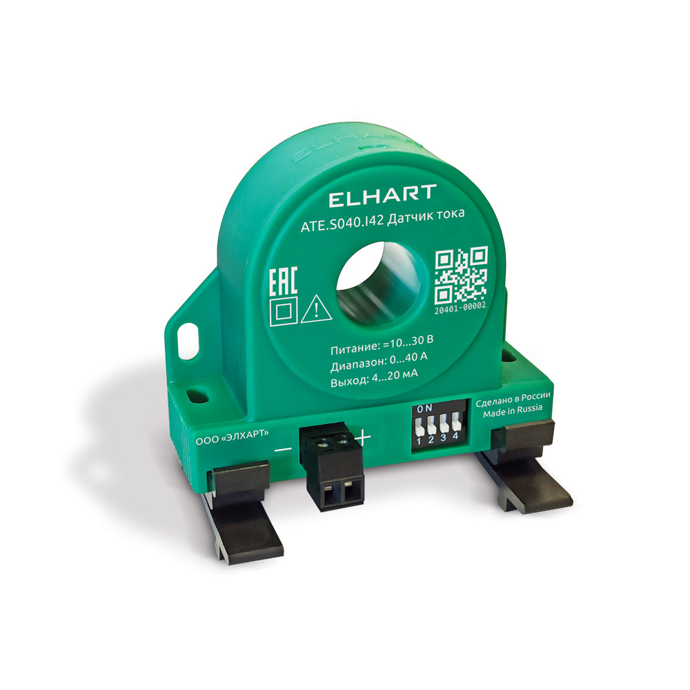
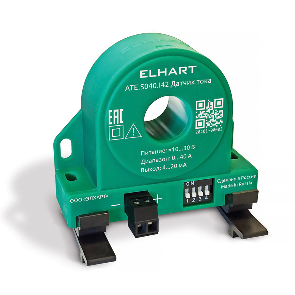
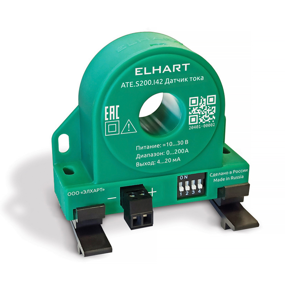
ATE.S is a series of non-contact AC current transducers with 4–20 mA output signal proportional to the measured primary current within the configured measurement range.
| Modifications | ATE.S040.I42 | ATE.S200.I42 |
|---|---|---|
| Measurement parameters | ||
| Measurement ranges (configurable) | 0...5 / 0...10 / 0...15 / 0...20 A 0...25 / 0...30 / 0...35 / 0...40 A |
0...25 / 0...50 / 0...75 / 0...100 A 0...125 / 0...150 / 0...175 / 0...200 A |
| Allowable overload | up to 600 A | up to 1000 A |
| Measured current frequency | 40…400 Hz | |
| Measured current waveform | sinusoidal signal | |
| Accuracy | ±0.2% for the smallest range, ±0.3% for the remaining rest |
|
| Output parameters / power supply | ||
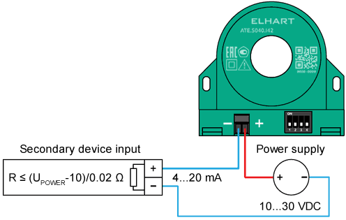
| Supply voltage | 10…30 VDC (loop-powered) | |
| Power consumption | max 1 W | |
| Output signal | 4…20 mA | |
| Response time | 0.1 sec without filtering, 2.5 sec with the filter on |
|
| Environmental Parameters | ||
| Ingress protection | IP20 | |
| Operating temperature | -20…+65 °C | |
| Connection, installation and configuration parameters | ||
| Configuration method | via DIP switches or additional wire turns | |
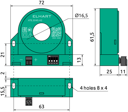
| Measured current connection | measured current cable passed through a ⌀16.5 mm center hole of the transducer | |
| AC dielectric strength | bare conductor: 3 kV / insulated conductor: determined by conductor insulation properties | |
| Overvoltage category | bare conductor: CAT III 300 V / insulated conductor: CAT III 600 V | |
| Power and output connection | Pluggable 2-pin terminal block for wire cross-section up to 2.5 mm² | |
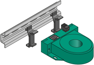
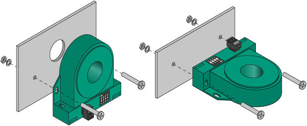
| Mounting | on a 35 mm DIN rail using mounting clips or surface mounting through fixing holes in the housing | |
| Input range | ||||
|---|---|---|---|---|
| 1 | 2 | 3 | Value | |
| ATE.S040 | ATE.S200 | |||
| 0…5 A | 0…25 A | |||
| 0…10 A | 0…50 A | |||
| 0…15 A | 0…75 A | |||
| 0…20 A | 0…100 A | |||
| 0…25 A | 0…125 A | |||
| 0…30 A | 0…150 A | |||
| 0…35 A | 0…175 A | |||
| 0…40 A | 0…200 A | |||
| Output filter | |
|---|---|
| 4 | Value |
| disabled | |
| enabled |
Possible configurations: