Motorized Valve PID Controllers ECV1 Series

Motorized Valve PID Controllers ECV1 Series

The ECV1 single-channel PID controller with universal inputs is applied across various industries, municipal, and agricultural automated control systems, and is designed for:
   — Operating motorized control valves, dampers, and electric actuators via 3-point floating (Open/Close) discrete control or 0/4…20 mA and 0/2…10 V analog signals.
   — Temperature measurement using thermocouples (TCs) according to GOST R 8.585-2001 and resistance temperature detectors (RTDs) according to GOST 6651-2009.
   — Measuring standard DC current and voltage signals and scaling them into user-defined engineering units (°C, %, bar, m, kgf/cm², etc.).
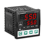
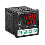
Modifications Where to buy?

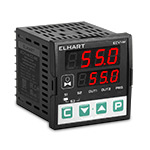
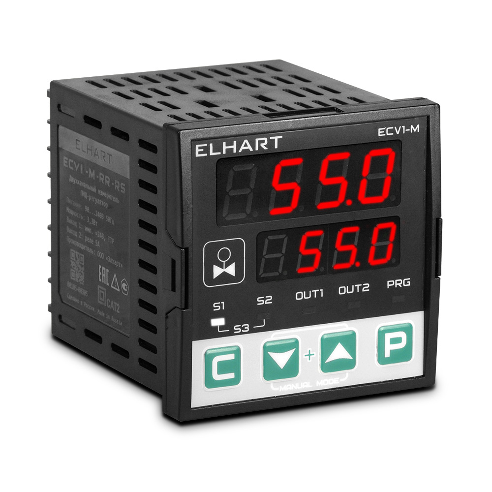
PID controller for shut-off control valves ECV1-M-RR-RS
ECV1-M-RR-RS
  • Design: size M (72×72 mm)
  • Inputs: 2×universal
  • Outputs: 2×relay
  • Communication interface: RS-485 (ModBus)
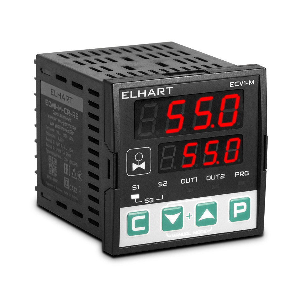
PID controller for shut-off control valves ECV1-M-CR-RS
ECV1-M-CR-RS
  • Design: size M (72×72 mm)
  • Inputs: 2×universal
  • Outputs: 1×analog, 1×relay
  • Communication interface: RS-485 (ModBus)
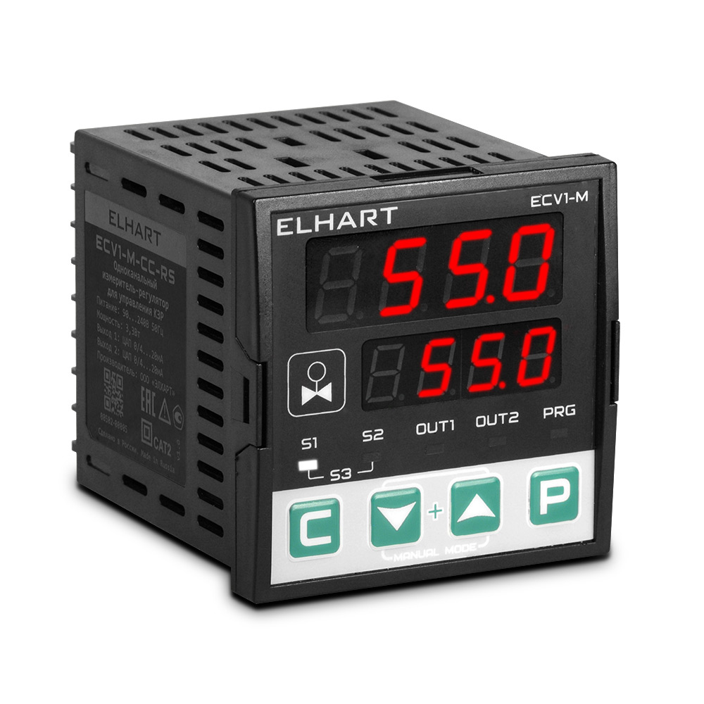
PID controller for shut-off control valves ECV1-M-CC-RS
ECV1-M-CC-RS
  • Design: size M (72×72 mm)
  • Inputs: 2×universal
  • Outputs: 2×analog
  • Communication interface: RS-485 (ModBus)
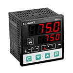
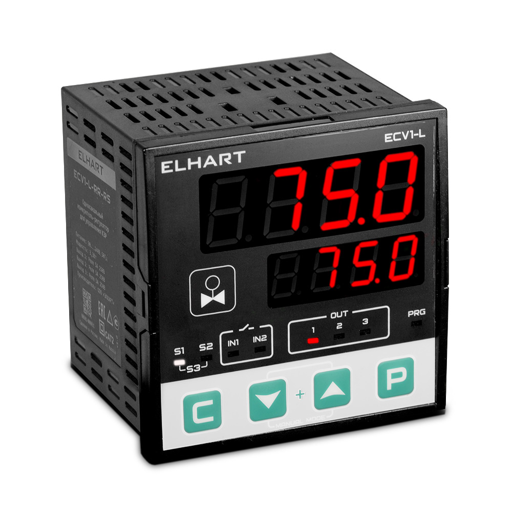
PID controller for shut-off control valves ECV1-L-RR-RS
ECV1-L-RR-RS
  • Design: size L (96×96 mm)
  • Inputs: 2×universal, 2×digital
  • Outputs: 3×relay
  • Communication interface: RS-485 (ModBus)
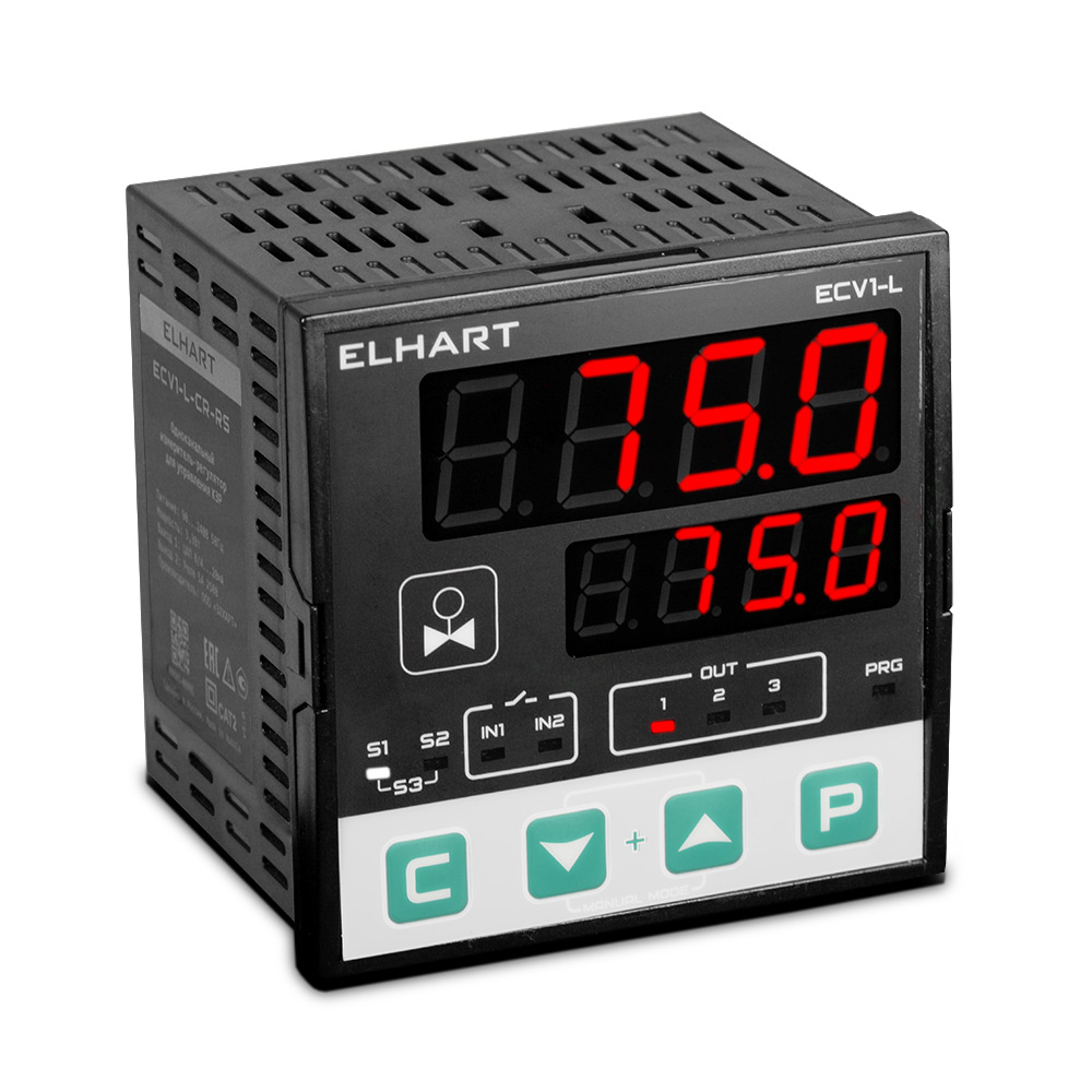
PID controller for shut-off control valves ECV1-L-CR-RS
ECV1-L-CR-RS
  • Design: size L (96×96 mm)
  • Inputs: 2×universal, 2×digital
  • Outputs: 1×analog, 2×relay
  • Communication interface: RS-485 (ModBus)
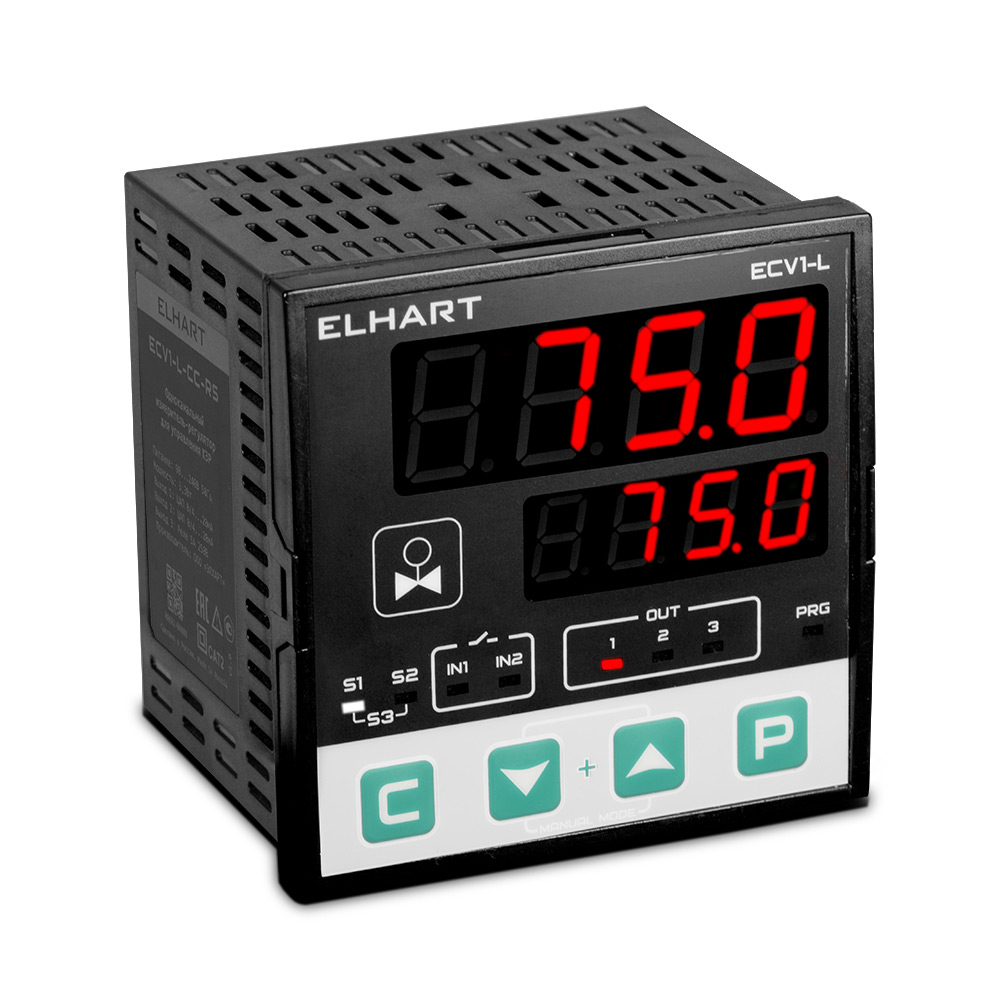
PID controller for shut-off control valves ECV1-L-CC-RS
ECV1-L-CC-RS
  • Design: size L (96×96 mm)
  • Inputs: 2×universal, 2×digital
  • Outputs: 2×analog, 1×relay
  • Communication interface: RS-485 (ModBus)
  • Functional diagram of ECV1 Motorized Valve Controller
    Functional diagram of ECV1 Controller
    Functional diagram of ECV1 Controller
  • Features of ECV1 Motorized Valve Controller
    • Motorized valves operating using 3-point floating control (Open/Close relays) or an analog signal.
    • PID, PDD2, and ON/OFF control modes are supported, as well as manual control.
    • Operation with valve position feedback.
    • Remote setpoint adjustment via external potentiometer, DC current or voltage signals.
    • Heating curve (weather-compensated control) and setpoint correction curve.
    • Advanced arithmetic capabilities: weighted sum, difference, ratio, square root.
    • Anti-freezing and anti-sticking protection for valves.
    • Three configurable screen sets for custom operator parameter display.
    • Configurable setpoint change rate (°C/min).
    • LBA (loop break alarm) function.
    • Multiple operator parameter lock levels.
    • Make-up pump control function in heating systems (for ECV1-L).
    • Valve limit switches support (for ECV1-L).
    • Built-in 24 VDC power supply for sensors with unified analog current and voltage signals.
  • Technical characteristics of ECV1 Motorized Valve Controller
    Modifications ECV1-M ECV1-L
    Overall dimensions (W×H×D) 72×72×88.2 mm 96×96×88.2 mm
    Number of measuring inputs 2
    Measuring inputs (universal) RTDs: Cu50, Cu100, Cu500, Cu1000, Pt100, Pt500, Pt1000, Ni100, Ni500, Ni1000
    TCs: L, J, K, R, S, T, N, B, A-1, A-2, A-3
    current: 0…5 mA, 0…20 mA, 4…20 mA
    voltage: -50…50 mV, 0…70 mV, 0…1 V, 0…10 V
    potentiometer (for Input 2): 500 Ω, 1 kΩ, 5 kΩ, 10 kΩ
    digital signal (for Input 2): "dry contact"
    Number of digital inputs 2
    Digital inputs "dry contact", NPN
    Basic error limit RTD and analog signals: ±0.25% of span
    TC: ±0.25% of span (without cold junction temperature compensation)
    DAC: ±0.15% of span
    Input polling time 0.3 s
    Built-in power supply 24 VDC, 40 mA
    Control modes ON/OFF (two-position), PID, Manual control, Alarm, Retransmission mode, PID-Fuzzy, PDD2
    Number of outputs 2 3
    Output type EM relay (5 A at 250 VAC, 3 A at 30 VDC, resistive load)
    active DAC: 0/4…20 mA, 0…5 mA (max load 850 Ω)
    Communication interface RS-485, Modbus-RTU protocol
    Ingress Protection IP54 (front panel)
    IP20 (housing)
    Environmental conditions Operating temperature: (-20...+50) °C
    Storage temperature: (-20...+50) °C
    Relative humidity: (0…80)% (without condensation)
    Supply voltage 90…240 VAC / 50 Hz (Nominal: 220 VAC / 50 Hz)
    Power consumption max 3.3 W
    Insulation category CATII (double insulation)
  • Connection diagram of ECV1 Motorized Valve Controller
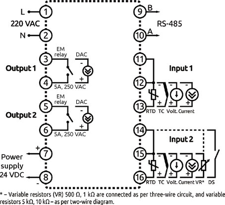
    Connection diagram of ECV1-M controller
    Connection diagram of ECV1-M controller
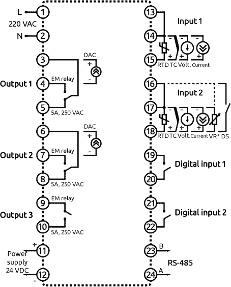
    Connection diagram of ECV1-L controller
    Connection diagram of ECV1-L controller
  • Overall dimensions of ECV1 Motorized Valve Controller
    Overall dimensions of ECV1-M controller, mm
    Overall dimensions of ECV1-M controller, mm
    Overall dimensions of ECV1-L controller, mm
    Overall dimensions of ECV1-L controller, mm